
Home›Products›Communications & Military›Telecom & Carrier Equipment›Lab-Volt / LabVolt 9444-00 PCM Encoder for Digital Communications Training Systems - Training / Education
Lab-Volt / LabVolt 9444-00 PCM Encoder for Digital Communications Training Systems - Training / Education
sku127981 — low stock
Request a Quote
By Lab-Volt
<p>The PCM Encoder converts an analog input signal to a digitally-coded output signal (pulse to PAM, PWM, and PPM), since the PCM output is in binary code. In PCM, an analog input signal is sampled and an 8-bit code is generated representing the input signal amplitude at each sample point. A b…
Description
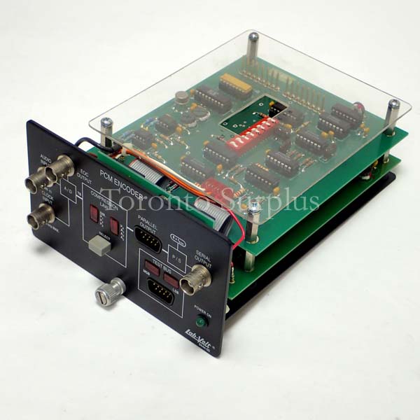
<p>The PCM Encoder converts an analog input signal to a digitally-coded output signal (pulse to PAM, PWM, and PPM), since the PCM output is in binary code.
In PCM, an analog input signal is sampled and an 8-bit code is generated representing the input signal amplitude at each sample point. A bar graph indicator for the test bus shows the logic states of the 8-bit A/D converter output. Both parallel and serial PCM outputs are provided for experimental work.
Using the PCM Encoder, students become familiar with the basics of A/D conversion and PCM signal generation.  Other important concepts, such as quantization error and volume compression are studied as well.
Specifications
Power Requirements: Connection to the Enclosure / Supply Regulator, Model 9420 (not included)
Audio Input
Voltage: 2 V p-p
Impedance: 600 Ω
Frequency Range: 300 Hz to 5 kHz</p><p>Clock Input
Maximal Frequency: 40 kHz
Outputs: Serial-bit parallel end of conversion (A/D converter)
Output Voltage: TTL</p><p>
Compression Modes</p><ul><li>4 Bell μ-type laws</li><li>3 CCIT A-type laws</li><li>Direct (no compression)</li></ul><p>Fault-Insertion Switches: 8
Test Bus: 1
Physical Characteristics
Dimensions (H x W x D) 83 x 142 x 212 mm (3.3 x 5.6 x 8.3 in)
Net Weight 0.9 kg (2.0 lb)</p>
In PCM, an analog input signal is sampled and an 8-bit code is generated representing the input signal amplitude at each sample point. A bar graph indicator for the test bus shows the logic states of the 8-bit A/D converter output. Both parallel and serial PCM outputs are provided for experimental work.
Using the PCM Encoder, students become familiar with the basics of A/D conversion and PCM signal generation.  Other important concepts, such as quantization error and volume compression are studied as well.
Specifications
Power Requirements: Connection to the Enclosure / Supply Regulator, Model 9420 (not included)
Audio Input
Voltage: 2 V p-p
Impedance: 600 Ω
Frequency Range: 300 Hz to 5 kHz</p><p>Clock Input
Maximal Frequency: 40 kHz
Outputs: Serial-bit parallel end of conversion (A/D converter)
Output Voltage: TTL</p><p>
Compression Modes</p><ul><li>4 Bell μ-type laws</li><li>3 CCIT A-type laws</li><li>Direct (no compression)</li></ul><p>Fault-Insertion Switches: 8
Test Bus: 1
Physical Characteristics
Dimensions (H x W x D) 83 x 142 x 212 mm (3.3 x 5.6 x 8.3 in)
Net Weight 0.9 kg (2.0 lb)</p>

